
DRIVEWAY GATES SPECIFICATIONS
* Prowell Woodworks is a product-based company. We are not available for site visits.
Quick Links to the 5 Driveway Gates Specifications Options
![]()
DRIVEWAY GATE SPECIFICATIONS
Printed Installation Guides and Working rawings arrive with all shipped or delivered orders
Driveway Gates Applications:
Option #1): 12′ or less overall width
Option #2): Beyond 12′, requiring exposed steel frame
Option #3): Beyond 12′, with embedded steel frame
Option #4): Sliding Gates, all widths–mouunting to single-span steel frame
More information is available on the Drive Gate Base Cost Tables
* Step by Step Full Installation Text
* Extenuating Circumstances
PDF Specifications
* Wood Gate Stops
* Setting Your Post
* Setting Jambs to Columns
* Embedded Jambs
* Setting Jambs to Steel Posts
Gate Hardware
(For Non-Automated Gates)
* Rocky Mountain Hardware
* Optional Bronze Hardware
Hydraulic Gate Closers
* Lockey TB175
* Lockey TB200
* Lockey TB600
Automated Armature Motors
* Apollo 1500 * FAAC
* Viking G5 Video
* Elite Viking G-5
* Elite Viking G-5 Solar
* FAAC
Security Access
![]() DRIVEWAY GATES SPECS
DRIVEWAY GATES SPECS
OPTION #1
NON-AUTOMATED
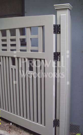
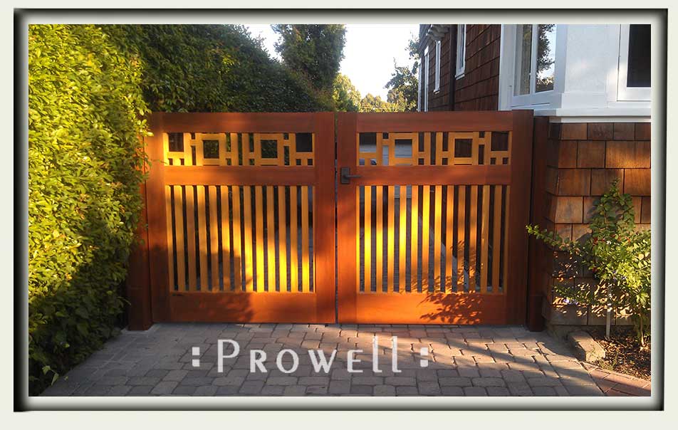
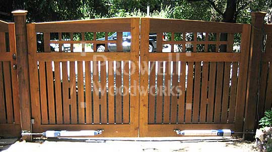
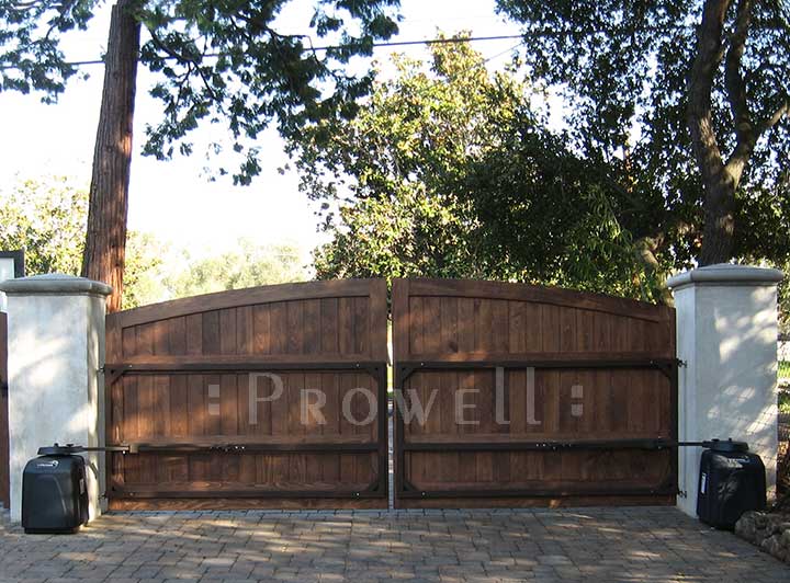
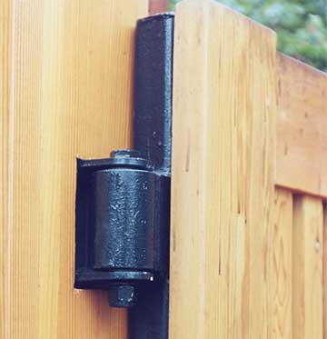
Option #1 Driveway Gates specifications are limited to 12′ overall width between columns or posts and do not require a steel frame. Gates are at 2-1/4″ thickness, and mounting with the bronze 4″ ball-bearing hinge to either Wood 6×6 posts, Steel posts, or jambs that are provided by Prowell and mounted to masonry columns. They normally utilize the same latch options and configurations as a pedestrian gate. They are installed with the same procedure as a double pedestrian gate. Gate openings of up to 12′ overall between posts or columns are two gate leaves at 6′ maximum each, which weigh approximately 125 lbs ea, depending on the gate style. Hinges are surface-mounted to the posts/jambs and gate to insure air flow on all six sides of the gate.
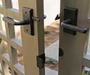
Driveway Gate style#12, as a manual swing, hinged to surfaced 6×6 posts. Stops mounted to the posts simply to conceal the hinge gap. Requires a cane bolt mounted to the inside of the fixed gate (normally the left gate), as well as a gate latch.
Driveway Gate #20, hinged to 6×6 posts. Here each gate leaf at 61″ wide x 60″ high. Functions as if it were a pedestrian double gate, using the Rocky Mountain latch, a Bronze cane bolt on the property side of the left, fixed gate, and three bronze ball-bearing hinges.
About half of you opt for a matching dummy latch on the left gate. Although providing symmetry, it can also confuse the first-time visitor as to which of the gates is the working gate.
AUTOMATED
Suggested solutions:
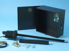
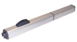
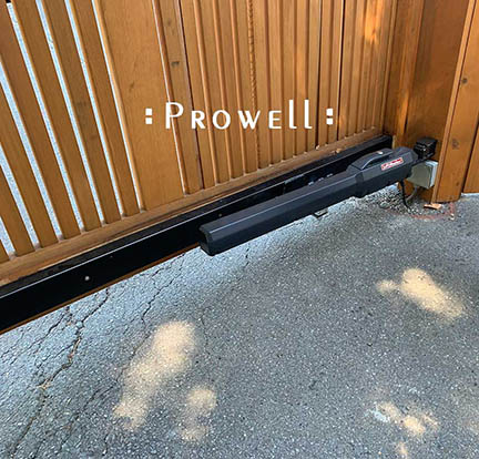
1. The LA500 by Liftmaster Linear Actuator. Attaching to the post and bolted to the gate.
2. The CSW24UL by Liftmaster. This is a big box that mounts inside the property and attaches to the gate with an articulating arm.Visible on the property side. Prowell will need to know where the arm connects to the gate (i.e. along the bottom horizontal rail or, if the arm is off the top of the motor, where it connects to the gate so we can add a full thickness lower stile for mounting)
3. The 770 by FAAC. This unit is underground and out of sight. Although it is underground, the device is highly serviceable, which is good because all in-grounds require regular maintenance to clear out the accumulating dust and debris.
PDF Download Spec Sheets
LA500 cut sheet spec
CSW24UL
770 FAAC
Prowell Woodworks does not provide automation for our Driveway Gates. The below specs are for your general information. If you are located in San Francisco’s north bay counties, Donovan Martini is a reliable referral
email: <sales@sculpturalgates.com>
A preview below of various manufacturers.
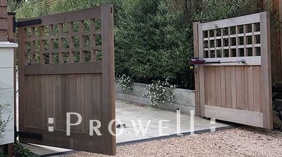
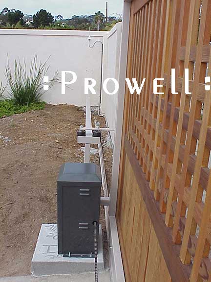
Mounted to the post with screws and the bottom rail of the gates with through-bolts. Mounted on the property side of the gates that swing in toward the property. Mounted to the street side if the gates swing out toward the street.
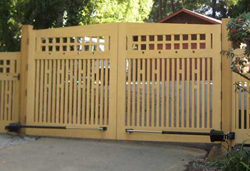
The Apollo 1500 equipped with an elbow, mounted on the property side, pushing the gates open toward the street. The advantage is you don’t see the motor from the street. The disadvantage is you lose clearance when the gates are in the opened position.
Click on the left-Margin links to the manufacturer specifications and ordering info.
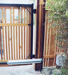
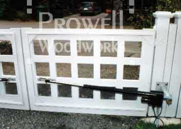
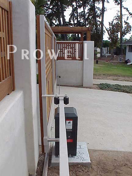
The Armature style motor on another example of outswing gates. Here the motors are mounted on the inside face of the gates, giving you a visual example of how the motor arm encroaches on the rough opening clearance.
Advantage: not visible from the street
Disadvantage: A loss of 4″-6″ clearance per armature.
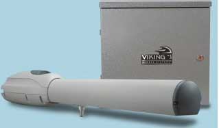
FAAC LINEAR ACTUATOR MOTOR
![]()
FAAC shown mounted from Prowell’s Column to a steel frame.
FAAC shown mounted on 6×6 posts to the gate’s bottom rails.
Click on the Left-Margin link for manufacturer specifications and ordering info.
Shown installed to a steel frame.
*P.S. When the gate are notably wider than their height, steel frames are required.
Click on Left-Margin link for more manufacturer specifications and ordering info.
T ypical LiftMaster Armature installed to a steel frame. Drive Gate #11-1
For more on the LiftMaster LA500UL model
Gate Safety and Security
Safety Reversing:
When detecting an obstruction the gate reverses with the inherent reversing sensor and the included monitored safety accessories.
Security+ 2.0®:
Safeguards access to a property with an encrypted signal and offer extended range with Security+ 2.0.
Quick Close Feature:
With installation of optional expansion board, prevent unauthorized access with quick close feature that stops vehicles from tailgating.
UL Listed:
Tested to the most stringent UL 325 industry guidelines. Secondary entrapment devices need to be added to meet UL325 standards. Your Installer will recommend suitable secondary entrapment devices for your installation, such as photo eyes or edge sensors.
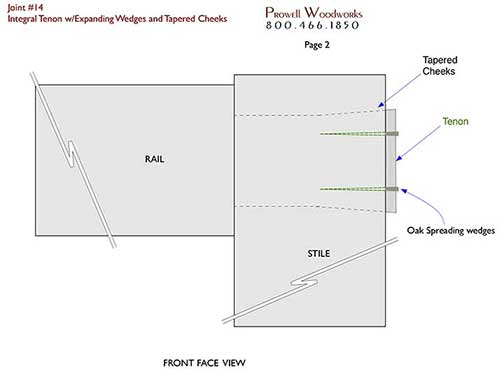
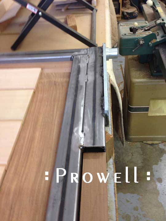
There are a number of joints utilized in a Prowell product. Some of them dating back centuries, while others are developed anew, geared to specific stress loads and application.
Below, Joint #14, is an integral tenon as an extension of the rail, fed through the width of the hinge stile mortise, which is tapered to accept the spreading oak wedges.
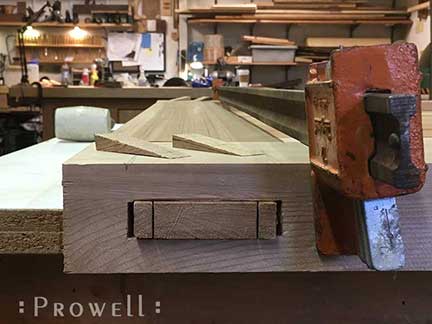
Once the wedges are driven in, and the tenon has spread to the edges of the tapered mortise, it becomes a locking joint. When the rain, humidity, fog, even dew absorb their moisture into the tenon, it thus expands, and the joint grows even tighter.
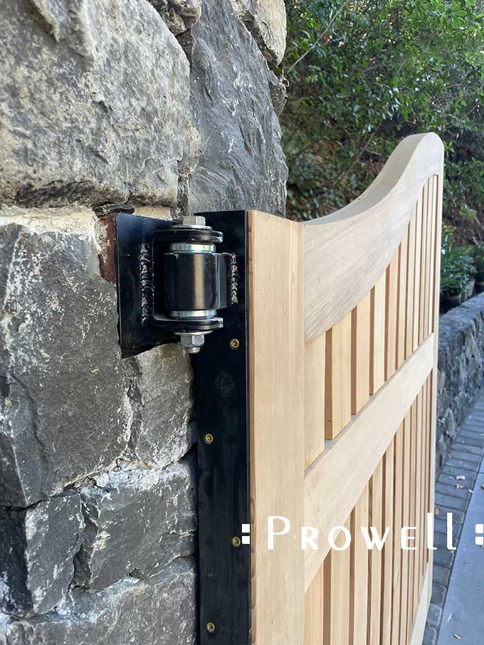
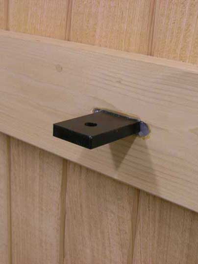
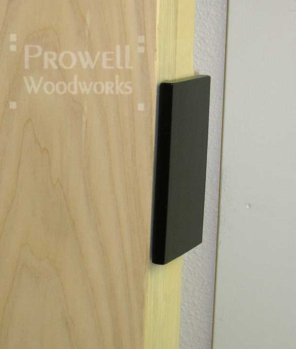
PIANO-HINGING SYSTEM

Option #1 gates that are lumber-heavy or, due to their design, put a greater stress load on the standard 4.5″ ball-bearing butt hinges, the ideal solution is the piano-style hnge shown below.
A continuous plate along the hinge stile (1/4″T) with multiple hinge screws, and an angle plate along the bottom extending approximately a third of the gate’s width.
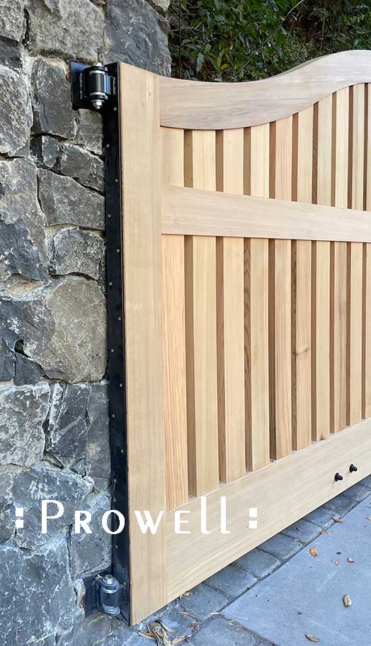
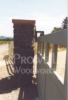
The hinge clearance depends on the automation contractor’s preferred hinge. Here we have 2-3/4″+/- from wood edge to the stone or wood post. With stone columns, the hinge is welded to the piano hinge and to a plate against the stone. The stone-mounted plate is welded to a steel T-bar that is in turn welded to the column’s steel post core.
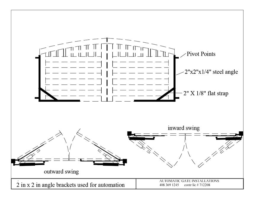
An illustrated example of the above steel frame as seen from the property side. Rick Dentoni of Automatic Gate Installations.
![]()
DRIVEWAY GATES
* Step by Step Installation Text
* Extenuating Circumstances
PDF Specifications--sketches
* T-Bar to colum
* Typical column /steel spec
* T-Bar with Knuckle Type Hinge
Automation Motors–sketches
* In-Ground Operators
Top hinge views
* In-Ground Operators #2
Top Pivot Hinge
Automation Motors–Links –In-Ground
* Viking 1-8 Dual
* SEA Compact 1600
In-Ground
—Above Ground (Pad Mounted)
Beyond 12′ overall width. 1-5/8″ thickness cedar–Requires steel reinforcing frame.
![]() DRIVEWAY GATES SPECIFICATIONS
DRIVEWAY GATES SPECIFICATIONS
OPTION #2
- Option #2 Driveway Gates specifications are almost always automated. Recommended motor: All-o-matic 325.
- With the exception of the In-Ground motors, automation can be added at any time after the driveway gates are installed.
- Option #2 motors are pad-mounted, Armature style motors, or In-Ground.
- All Option #2 Driveway Gates are mounted to an exposed hollow tube steel frame. Normally 2″ x 2″.
- Steel frames can often require a vertical piece that is placed so a pad-mounted motor arm can be mounted.
- Hinging systems are provided by the installer and welded to the steel frame.
- Hinging off steel posts or steel core masonry columns. Wood posts are insufficient.
- The hinge system is at the discretion of the installer or automation contractor. We will provide any plates or mounts upon request. (The hinge edge of the steel frame is flush with the edge of the gate). Whatever hinge system is preferred, we will require the specified clearance, which in turn determines our net gate widths.
STEEL FRAMES
Driveway Gates #13. Dual pad-mounted motors for a bi-parting swing. Motor arms welded to vertical steel supports. In this example, the vertical supports are aligned with the vertical wood grid dividers.
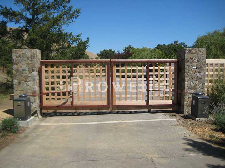
Driveway Gates #19. An 26′ overall span. Two bi-parting steel frames. Two wood gates mounted to each steel frame. Pad-mounted motors.
Driveway Gates #16-5 as a single span steel frame as well as the wood gate. Viking G-5 armature motor.
Driveway Gates #6-2. With arched top rails, the steel frame aligns to the highest horizontal rail. Here the middle horizontal steel rail happens to align with the motor arms.
OPTION #2 HINGES
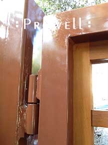
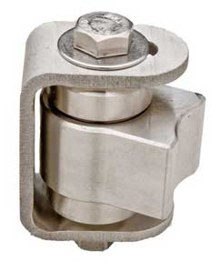
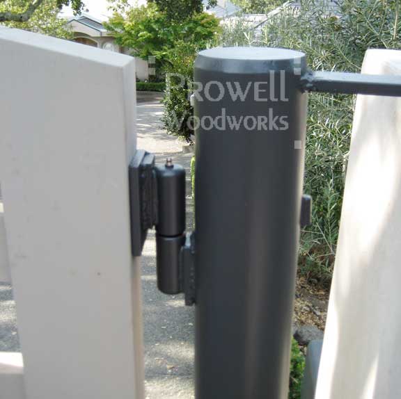
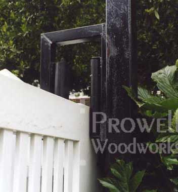
Knuckle Hinge. The most common hinge, swings with stainless ball-bearings. Shown with the steel post, the hinges, and the steel frame have all been painted.
The stainless “Shut It” hinge #304 by D&D Technologies. Also referred to as the ‘BasAss’ hinge. One edge welds to the steel post or a steel mounting bar, and the other, concave edge welds to the gate plate. A much less commonly used hinge. Click the image for more info.
A cylindrical Knuckle Hinge mounted to a round steel post and to the exposed plate for an embedded Option #3 gate.
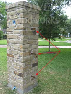
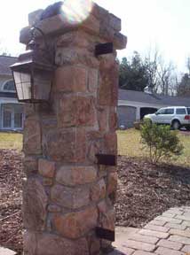
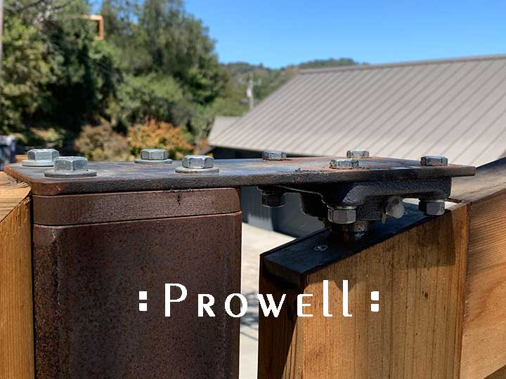
T-BARS
Typically the T-Bar is welded to the column core 6×6 hollow steel post as the columns are being built. It extends beyond the stone longer than necessary and is cut (torched) to the correct length when welding the hinge system to the exposed steel frame.
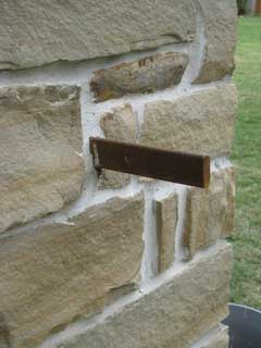
Normally there are two T-Bars, accommodating two hinges. Below they have elected for three T-bars, and three hinges.
If your columns are existing, there is always the chance that it may not have been built with a steel post core. Because it’s hard to know, your contractors may make a judgment based on the age of the columns and elect to either set new steel posts to the inside behind the columns and hinge the gate from that. The older existing stone columns are a gamble–they may or may not be worthy of supporting the new gate over the long haul.
![]()
DRIVEWAY GATES
* Ditec ‘ Cubic’ In-Ground Automation
* Ditec ‘ Cubic’ Technical Manual PDF download page
PDF Sketches
Cubic 6H-6HV In-Ground
Beyond 12′ overall width. 3″ thickness cedar- Embedded steel reinforcing frame.
![]() DRIVEWAY GATES SPECIFICATIONS
DRIVEWAY GATES SPECIFICATIONS
OPTION #3
- Option #3 driveway gates specifications are always automated. Armature, above-grade, or In-Ground motors.
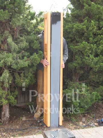
- The construction process is essentially four gates. Each gate leaf is two fully constructed and mortised gates that are routed to accept the inner steel, and then laminated together to create a 3″ total thickness.
- With the exception of the In-Ground motors, automation can be added at any time after the driveway gates are installed.
- All Option #3 Driveway Gates have their steel frames invisibly embedded within the framework of the wood gate.
- For Pad-Mounted motors, hinges weld to steel plate exposed along the edge of the gates.
- Hinging off steel posts or steel core masonry columns. Wood Posts are insufficient.
- The hinge system is at the discretion of the installer or automation contractor. Prowell will provide any plates or mounts upon request. Whatever hinge system is preferred, Prowell will require from the installer their preferred clearance, which in turn determines our net gate widths.
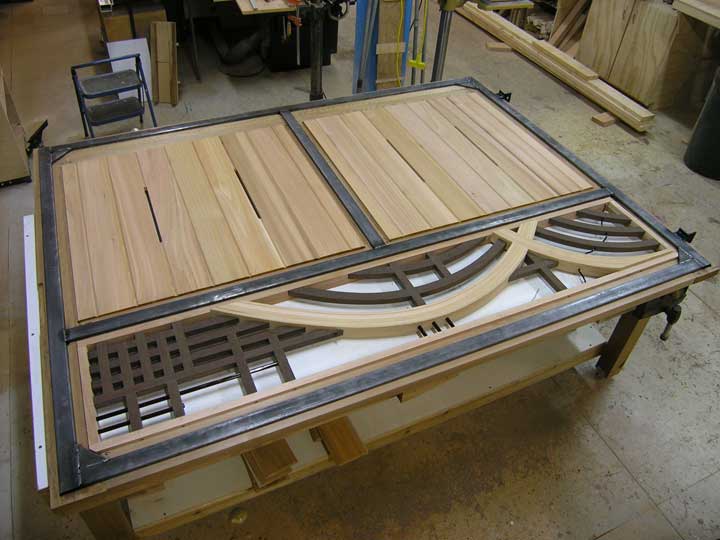
METHODOLOGY
A few years of trial and error prototypes lead to Option #3, allowing greater spans without visible steel reinforcement. Below we see half of one gate leaf before the mirrored half is laminated in place.
IN-GROUND AUTOMATION
In-Ground automation. The bottom motor plate welded to the steel frame extension of an embedded gate. PO#1545.
Motor: FAAC 770: (formerly Viking I-8). *Prowell does not provide the In-ground motors or the steel plates. We will, however, pocket-mortise the gates to accept the steel plates, as shown.

The same in-ground motor plate shown welded to a single flat-bar steel plate 24″ long for a non-embedded gate w/o a steel frame. This would be for gates that are 12′ or less for the overall opening. (PO#1736.). *Again, Prowell will mortise the gates to accept the the flat-bar plates but does not provide the plates themselves.
IN-GROUND MOTORS
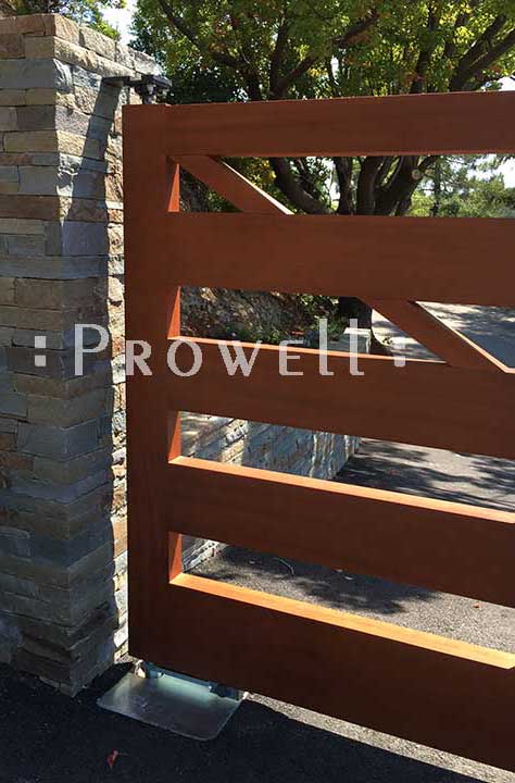
Driveway Gate Style #34 shows the hinge edge, with the lower In-Ground pivot hinge and the top stationary pivot hinge.
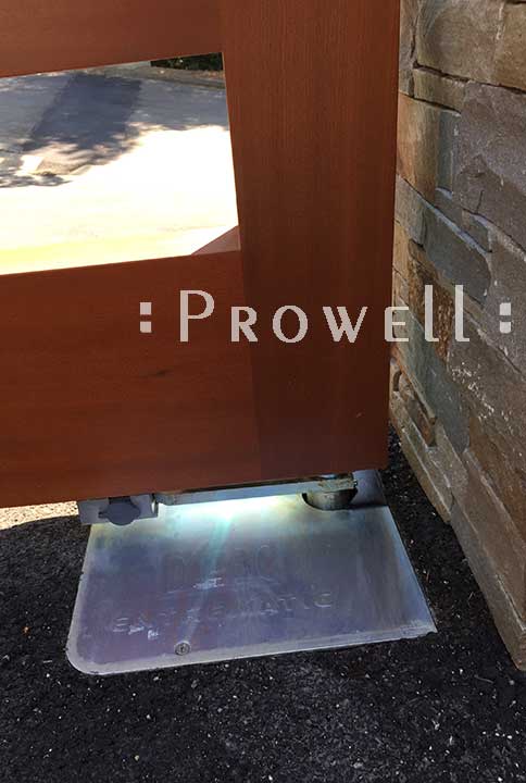
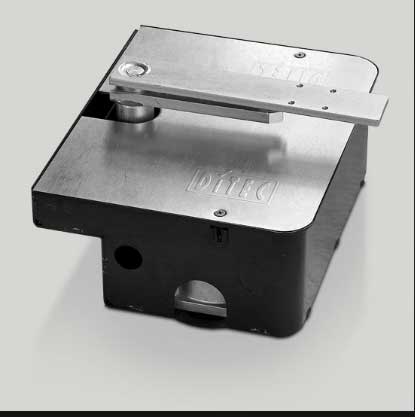
A closer look at the In-Ground motor as it appears once installed. The Viking 1-8, or CUBIC 6H-6HV (by Ditec Entrematic). They both have identical specifications. (Note: Viking was bought by FAAC. The Viking I-8 has been renamed: FAAC 770. )
NOTE: In-ground motors require regular maintenance every two years to clean out the dust and filaments from the gears.
The CUBIC 6H-6HV and Viking 1-8.(Since FAAC buyout in 2024, re-titled FAAC 770)
>To Ditec Manual
This is the identical unit as the Viking 1-8 and FAAC 770.
To Viking web site
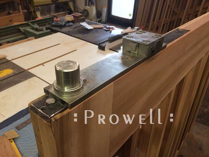
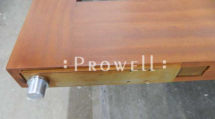
Typical top pivot mount for embedded driveway gates. A stainless steel plate mortised flush into the top of the hinge stiles and welded to the embedded frame. A stainless 1′ dia. dowel extending proud of the top. The pivot plate is set at the exact same set-back as the
The bottom pivot plate, mortised in at the specified distance to align with the In-Ground housing.
The motor Operational Arm ( shown with cylinder pivot pin) welds to the steel plate on site. The Operational Arm is normally about 14″ length, and although the plate shown below is not much longer, we suggest this plate be 24″-30″ in length, countersunk-bored to accept #12 for all-wood gates. For embedded steel gates, we prefer having the Operational Arms shipped to us so we can have our metal fabricator weld it to the steel frame prior to the gates being laminated to encase the embedded steel.
The top diameter pivot pin, set to align with the top stationary pivot hinge plate. Welded to the primary embedded structural frame.
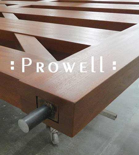
The frame with the extension tube and bottom pivot plate welded to specs prior to laminating the mirrored half of the wood gate.
*Below showing why it’s best to have Prowell’s metalworker weld the Operational Arm to the embedded steel prior to laminating the wood gates together.
WELDING PLATES
For embedded steel gates opting for standard pad-mounted motors we mortise a small mounting plate welded and mortised out from the primary steel to accept the motor arm.
And to weld the knuckle hinges to the T-Bars or steel posts we weld a mounting plate to the inner embedded frame, leaving it proud of the wood so the welding on site doesn’t burn the cedar.
Shown again here, with the knuckle hinge welded to the plate, and the round steel post.
![]()
DRIVEWAY GATES
* Step by Step Full Installation Text
* Extenuating Circumstances
PDF Specifications--sketches
Automation Motors–Links
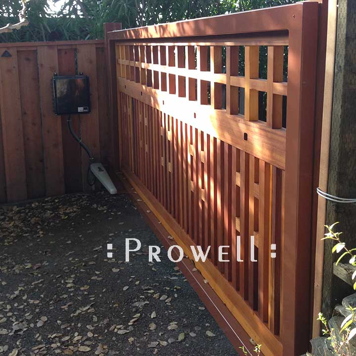
Sliding Driveway Gates. No Maximum Overall Width.
![]() DRIVEWAY GATES SPECIFICATIONS
DRIVEWAY GATES SPECIFICATIONS
OPTION #4
- Option #4 driveway gates specifications for sliding gates mounted to single-span exposed steel frames.
- As a pair of steel frames with each frame sliding away from the center.
- You must have the parallel clearance equaling the gate span.
- The gate will ride on a 1″ V-Track installed by your contractor into the driveway surface and extending the span of the slide.
- The gate’s vertical alignment is by either dual rollers mounted to the post/column, or a secondary track running parallel to the slide direction.
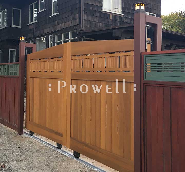
DUAL POSTS–BI-PARTING SLIDE
Driveway Gate #29 shows dual steel posts with mounted dual rollers. The gates part away from the center on a track that extends the width of each gate to the left and right, utilizing adjustable height rollers that are bolted or welded to the steel posts.
Because these gates are only 72″ width each, the need for a steel frame was not required. If the overall width is not beyond 12′, bi-parting sliding gates DO NOT require that each gate be mounted onto a steel frame.
If they were sliding together as a single gate to the left or right, a single-span steel frame would be required.
ALIGNMENT ROLLERS
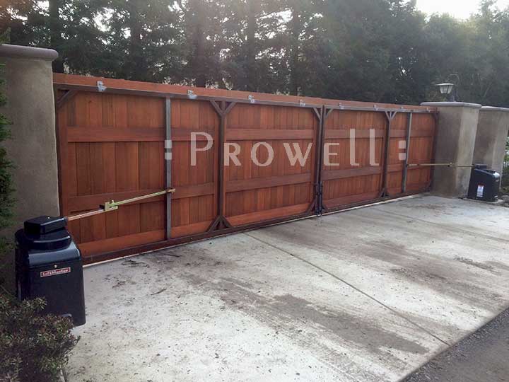
Example of the Dual Rollers riding on a Secondary Alignment Track. The rollers are welded or bolted to the gate’s steel frame, and sandwich the lower secondary to maintain the gate’s vertical alignment. This requires you have the space needed for the lower secondary track, usually set at a height of about 20″-24″ off grade.
The steel frame is a single span frame, exposed on the property side, with the two wood gate leaves surface-mounting onto the frame. Upon approach, it appears as a standard bi-parting double driveway gate.
Examples of dual rollers mounted to the back of the columns or posts. In this set-up, the rollers ride across the top of the wood gate.
The advantage is the elimination of the secondary track shown above. The disadvantage is the possibility of the rollers blemishing the wood finish over time.
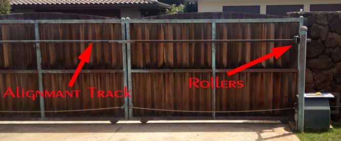
A third option represents photos sent in from a Hawaii inquiry to replace the below sliding gate. Here the Alignment Track is welded directly off the main steel frame.
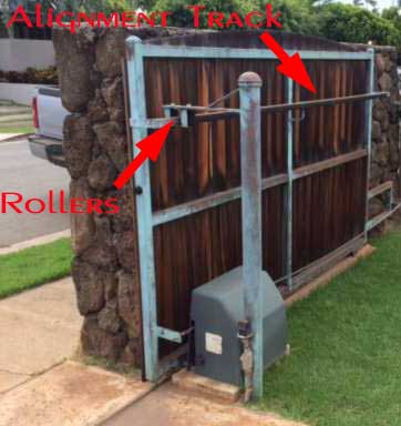
Although this is not an option we’ve seen used elsewhere, it makes a lot of sense. Eliminating the real estate required for the Secondary Track shown above, as well as a solution that keeps the rollers from direct contact with the gates. The Alignment Track below is held off the main frame by about 4″–room enough to accommodate the thickness of one roller.
SINGLE-SPAN STEEL FRAMES
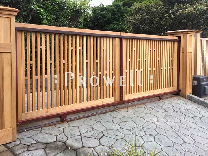
A typical single-span steel frame. A pair of wood gates mount to the frame and slides left or right as a single moving assembly.
A) If the overall opening is 12′ or less and the two wood gates slide open in opposite direction, no steel frame is needed.
B) If the opening is 12′ or less and the two gates want to slide as a single assembly left or right, a single-span steel frame is required
C) If the opening is greater than 12′ overall, as shown below, steel frames are required if the two gates slide open in opposite directions, OR, if the entire assembly slides to the left or right.
![]()
DRIVEWAY GATES
* Step by Step Installation Text
PDF Specifications
Various Mounting Applications
To Driveway Gates
*To Embedded Steel Frame
*To Exposed Steel Frame
*Mount to Lighted Columns
*Mount to Unlighted Column
To Pedestrian Gates
Mounting to Prowell’s Wood Gate Columns.
![]() DRIVEWAY GATES SPECIFICATIONS
DRIVEWAY GATES SPECIFICATIONS
OPTION #5
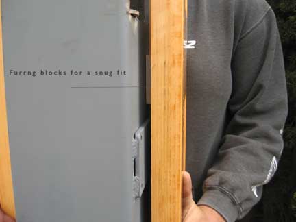
Prowell’s Columns arrive with one side temporarily in place. Removed on site to allow the column to slip around a wood or steel post. The columns are sized with blocking to fit your specified site post. The standard outside dimension is 10-1/8″ square. Prowell does not provide the lighting fixtures.
Fitting the 3-sided column around a steel post.
The Columns arrive with blocks furred to a snug fit to the given specifications of the site post.
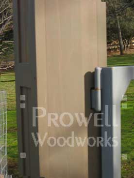
A Column mortised to accept a hinge support that has been welded to the steel post.
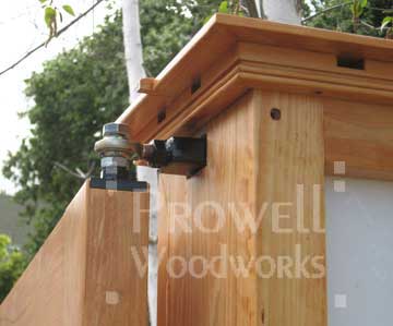
The adjustable Sleeve Hinge shown mortised through the column for an In-Ground Operator.
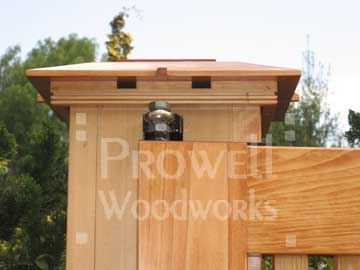
In-Ground Operators require a hinge placement to pivot on the top of the gate. Prowell provides the steel plate mounted to the top of the gate stile.
Knuckle style hinge shown mortised through the column and welded to the edge of the steel frame. It is this face that’s removable, so it can slip over the hinge T-Bar.
INSTALLATION REFERRALS
What we’ve learned over the past few decades:
1) Recommending an installer who may have been involved with another of our projects in any given area intimates that we know and trust him, when in fact we know nothing of him. He was simply the installer secured by a previous homeowner to install their project.
2) Recommending an installer we’ve never met who consequently visits your site is to present this installer as your first and only face-to-face connection to Prowell Woodworks. He may show up late, or not at all or perform the work ingloriously. He may be rude or unintelligent. His behavior impacts your impression of Prowell Woodworks.
3) Third-party installers regularly attempt to sway the homeowner against Prowell Woodworks in lieu of being hired to provide a facsimile of the same work themselves for a better price. Facsimile is the key here. We’ve lost innumerable projects due to this phenomenon. The homeowner must often be determined, insisting on what they want.
4) Recommending an installer associates Prowell Woodworks with that installer as if we were business associates and therefore liable for his or her workmanship.
5) We will often hear from whomever you eventually hire. They will call or write to check specifications or present a list of questions, which we will answer promptly. There is no link to competency or incompetency between those who reach out with questions and those who do not. What we can determine, from contact with your installer by phone or email, is their level of skill. Their level of experience in the trade.
6) Homeowners who are their own installers should understand they are welcome to call or write with their own questions and concerns, before or during their installation. For the most part, we will review that process over the course of your order. It should be noted that approximately half of all gate orders are installed by the homeowner themselves. Driveway Gate installations are best performed by qualified carpenters or contractors. The majority of fence installations are performed by carpenters or contractors, although it’s not uncommon for the homeowner to approach this.
7) With your finished product will arrive a packet that will include: Appropriate Installation Guides; A reminder sheet of the most common mistakes made during installation; and the same dimensioned drawings that were originally approved prior to fabrication in the shop.
* If by chance you happen to live within the San Francisco Bay Area, ignore the above ramblings. You’ll have the luxurious option of utilizing our long-time installers and automation contractors. Although they are separate entities in themselves, they have been associated with Prowell installations for many years.
PRODUCT SPECIFICATIONS NAVIGATION
![]()
Garden Gates
![]()
Driveway Gates
![]()
Fence Panels
![]()
Porch Swings
![]()
Columns
![]()

Hardware
![]()